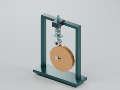
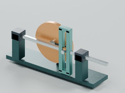
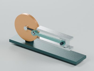
四槽槽轮分度机构
四槽外槽轮:拨销分度与共轭凹圆弧停歇锁止分层展示。
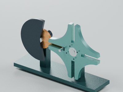
What is it made of?
01 机架、双轴承座与衬套
两个真实通孔支座保持中心距;青铜衬套内径0.51,轴径0.49。
02 有轴肩曲柄与滚套拨销
曲柄位于工作轮后层;拨销芯轴贯穿青铜滚套,端面垫圈轴向保持。
03 同轴锁止盘与退让口
连续圆周与槽轮共轭凹弧配合;38°半角退让区让开驱动期间的轮齿。
04 四槽输出轮、凹锁弧与轮毂
径向槽具有圆底;四段凹弧均以停歇时输入轴为圆心,不用平盘冒充锁止。
How do the parts work together?
d=4.2,r=d/√2;输入−45°到45°驱动输出反向90°,其余270°停歇。锁盘半径2.30,槽轮凹弧半径2.31,径向间隙0.01。
d=4.2,r=d/√2;输入−45°到45°驱动输出反向90°,其余270°停歇。锁盘半径2.30,槽轮凹弧半径2.31,径向间隙0.01。
Model scope and approximations
AI-assisted educational schematic, not manufacturing CAD. Materials, proportions and movements are limited to this model's description.
解析理想分度不计算0.03销槽侧隙及0.01锁弧间隙引起的回差。锁盘38°扇形退让口经离散全周期净空校核,是非制造用教学轮廓;未分析冲击、弹性或公差。
Sources
- Primary academic mechanism reference
CMU §8.4 describes quarter-turn output per driver revolution, pin in slots, and circular locking portions with a driver cutaway. Analytic engagement follows the pin angle about the driven center. Lock profiles are illustrative and unvalidated for manufacturing clearance.